![]()
This section provides a detailed description of the ePipe hardware and software setup and configuration required before using ePipe.
For first time users of ePipe and to use ePipe's Feature Sets, we recommend that you should be familiar with the Key Networking Concepts included in this documentation. These concepts will give a more in-depth explanation of networking fundamentals, concepts and scenarios.
Important note for all ePipe ServerWare
users:
During installation of the software, ePipe ServerWare detects the hardware
used by the computer. It is therefore important that the computer running
the software has all the hardware (Network Interface Cards, Stallion
Easy IO cards, Bootable CD ROM Drive, etc.) in the machine prior to installing
the software.
Refer to the Quick Setup Guide that is included in the ePipe kit before proceeding with hardware setup. The Quick Setup Guide contains a description of parts contained in the ePipe kit together with other requirements for connecting hardware. After hardware setup is complete, recheck each step in the Quick Setup Guide before continuing on with software setup and configuration.
The ePipe Management Assistant is the web browser based Graphical User Interface (GUI), enabling software setup and configuration of the ePipe or ePipe ServerWare through a series of setup wizards. This is the recommended way of configuring the ePipe. See the Software Setup section for more information.
![]()
A printed copy of the Quick Setup Guide appropriate to each ePipe model is shipped with each ePipe kit. It contains a checklist of parts contained in the ePipe kit together with other requirements for connecting hardware and configuring the software of the ePipe.
After hardware setup is complete, recheck each step in the Quick Setup Guide to ensure correct setup before continuing on with software setup and configuration.
The Quick Setup Guides for all ePipes are included below:
ePipe 2148/2188 [PDF - 1487 KB]
![]()
To view Adobe Acrobat Reader PDF files, download Acrobat Reader.
![]()
 General
Information
General
Information ePipe is a scalable Internet gateway and VPN router which can use a broad range of connection technologies for connecting to the Internet. The ePipe 2000 devices currently are divided into the 2100 Series, 2200 Series, and 2300 Series. ePipe ServerWare is a software version of the 2000 series devices. Both series have some common hardware features and these are described below:
Ensure that the computer that will be running ePipe ServerWare meets the minimum system requirements. These are as follows:
| Model | CPU | Memory | Disk |
| Concentrator-10 | 400MHz Pentium III | 64MB | 1.2GB |
| Concentrator-50 | 700MHz Pentium III | 64MB | 1.2GB |
| Concentrator-150 | 700MHz Pentium III | 128MB | 1.2GB |
| Concentrator-500 | 700MHz Pentium III | 256MB | 1.2GB |
ePipe ServerWare will require a Network Interface Card (NIC) to connect to the LAN. Supported Ethernet card chipsets include:
| EthernetExpress Pro/100 | SiS 900/7016 |
| PCI NE2000TI | ThunderLAN |
| AMD PCnet32 | DECchip Tulip |
| RealTek 8129/8139 | VIA Rhine |
If connecting to the Internet via PSTN modems or ISDN terminal adapters, you will need sufficient serial ports to deliver the desired aggregated bandwidth. ePipe ServerWare will support up to 8 high performance serial ports using Stallion Technologies EasyIO products. If multiple Ethernet segments are required for bonding multiple ADSL connections, Demilitarised Zones (DMZ), etc. additional NICs will be required. Install all necessary hardware prior to installing ePipe ServerWare.
Different PC and server motherboards rarely address their PCI ports in the same way. When using multiple NICs, it is impossible to predict which Ethernet segment will be Ethernet 1.
To assist in identifying the sequence of NICs installed in the ePipe ServerWare computer, you will need to obtain the MAC address of each Ethernet segment and record the position of the associated port where it can be referenced. During installation of the software, an IP address will be assigned (either manually or automatically) to Ethernet 1.
You will be able to ascertain the addressing of each Ethernet port by using the console connected to the ePipe ServerWare computer. Enter root as the username and system as the password. Now enter the command
SHOW ETHERNET
and ePipe ServerWare will show the port allocation for each NIC. This information can now be cross-referenced with the MAC addresses that were recorded prior to installation.
Before you can install and setup ePipe ServerWare, you need to be aware of the type and configuration of network to which the server will be attached. If you are setting up a new network then proceed to the next section New Networks. If you already have an existing network then proceed to the section Existing Networks.
ePipe ServerWare can be used in a new network. It is important to first design the network and ensure that you have all the hardware and cabling required. Due to the potential complexity of computer networks and the vast number of variables for such a network it is not feasible to provide explicit examples in this documentation. The single factor that is consistent however, is the typical position of ePipe ServerWare in the network.
ePipe ServerWares function as an Internet gateway, bandwidth aggregator and firewall will typically see the ePipe ServerWare computer situated between the LAN and the Internet.
It is assumed that users of ePipe ServerWare will have sufficient knowledge to design and build a LAN.
ePipe ServerWare can be introduced to an existing network. A decision will need to be made on where within the network ePipe ServerWare will reside. This decision will be based largely on the function of ePipe ServerWare in the network. For example, if being used as a bandwidth aggregator, firewall and Internet gateway, the ePipe ServerWare computer would be situated between the LAN and the Internet. When used simply as a VPN terminating device or Internet access is provided by an existing router or firewall, ePipe ServerWare can be situated in a DMZ, on the LAN, or between them, acting as a firewall protecting the LAN from the DMZ.
Due to the potential complexity of computer networks and the vast number of variables for such a network it is not feasible to provide explicit examples in this documentation.
It is assumed that users of ePipe ServerWare will have sufficient knowledge to determine the most appropriate location for ePipe ServerWare within the network.
The serial ports on the ePipe ServerWare computer allow you to connect many different serial devices. These devices include:
The Ethernet ports used in the ePipe ServerWare computer could be used to connect the following:
All hardware is detected during the ePipe ServerWare installation process.
Any changes to the hardware used in the ePipe ServerWare computer will require
re-installation of the software. Be sure to save the ePipe ServerWare
configuration prior to re-installation using the eConfig software on the ePipe VPN and Security Family
Software and User Documentation CD included with ePipe ServerWare
or available from the downloads section
of the ePipe website.
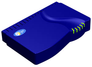
The ePipe is a desktop style unit with an external power supply and can be located on any flat stable surface and can also be wall mounted using the wall mounting slots. The diagrams below describe the physical characteristics of the ePipe. The physical description of the rear of each ePipe can be found in the ePipe Family sections following this section.
|
The base of the ePipe has product labels and other product information including serial and sub-lot numbers. Note the Ethernet or MAC address label as this information will be required when enabling optional feature sets. Wall Mounting InstructionsThe vertical wall mounting slots can be used with standard flat-head screws for mounting on walls or other surfaces. When mounting, ensure that the screws and wall will hold the weight of the ePipe and any attached cabling. Use a minimum of No. 8 screws and anchors of a minimum of 3/4 inch (180 mm) in length when mounting the ePipe to plaster board surfaces. For other types of surfaces, use suitable screws and fasteners to secure the ePipe.
|
| The LEDs on the front of the ePipe are also visible from the top making the unit's status clearly visible. The LEDs are shown in the diagram to the right and their function is explained below. |
|
The LEDs on the front/top of the ePipe have the following meanings:
| PWR | Power LED indicates the the power supply is connected and on. This is normally active. | ||
| RUN | Indicates the unit is running and operational. This is normally active. | ||
| RXD | Indicates data is being received on one of the serial ports or the console port. Normally flashes as data is received. | ||
| TXD | Indicates data is being transmitted (sent) on one of the serial ports or the console port. Normally flashes as data is sent. | ||
| NET | Indicates network activity on the hub or Ethernet ports. Normally flashes as data is received. |
The ePipe 2100 Series models have one routable Ethernet interface (in the form of an eight (8) port hub), and either four (4) or eight (8) RS-232 asynchronous serial ports. The 2100 Series is best suited to offices which need access to the Internet via dial-up analogue (PSTN) phone lines or ISDN.
There are three (3) models in the ePipe 2100 Series. These models are the 2148, 2188 and 2181. The model numbering uses a convention that generally indicates the model and types of ports. The initial "2" indicates the family and represents the ePipe 2000 family. The 1 indicates the 100 series. The last 2 digits indicate the number of serial (RS-232) ports and the number of Ethernet or Hub ports respectively. Thus the 2148 is part of the 100 series of the 2000 family and has 4 serial ports and 8 Ethernet hub ports.
The ePipe 2181 has 8 serial and one 10/100 Mbps Ethernet port while the 2148 and 2188 have eight 10 Mbps hub ports each.
The picture below shows the rear view of the ePipe 2188. The Ethernet hub ports on the ePipe are marked "10BaseT LAN" with a green label and are on the right hand side of the unit (as viewed from the rear). The Serial ports are grouped in a block of 4 or 8 on the left hand side of the unit (as viewed from the rear) and are marked "RS-232 serial" with an orange label. All 10Base-T and RS-232 ports are numbered above or below the port.
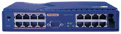
The diagrams below explain the connectors and external features on the rear
of the ePipe 2188 and 2181. The ePipe 2148 is the same as the 2188 except
that there are only 4 RS-232 serial ports.
The rear view of the ePipe (shown above using an ePipe 2188) shows the serial and Ethernet ports as well as the console port and Ethernet Hub Link LEDs. Note that the ePipe has a Kensington security slot for physical security and power supply jack holder which turns to prevent the power supply lead from inadvertently being pulled from the unit. Also take special note of the Erase button on the rear bottom left of the ePipe. This button is recessed and can only be depressed using a narrow straight object. When depressed (while the unit is powered on), the Erase button will erase the NVRAM (Non-Volatile Random Access Memory) of the ePipe which will erase all user configuration and reset the ePipe to the factory defaults. This will not affect feature set configuration.
The Hub Link LEDs are dual link and activity LEDs. If an active Ethernet connection is detected then the LED will light up in green. If there is network activity then the LED will flash (in green) while sending/receiving data on the port.
The ePipe 2181 is different from the 2148 and 2188 in that it does not have an internal hub. Instead it has a single auto-sensing full duplex 10/100 Mbps Ethernet port with four (4) status LEDs. The diagram below shows the rear of the 2181.
The LEDs on the left of the 10/100Base-T Ethernet port are described below:
 |
|
Similar to the 2100 Series units, the 2200 Series ePipes also have a Kensington Security Slot for the attachment of a Kensington lock that will prevent theft, a DB9 serial console port for configuration and management and a rotating holder for the power supply jack to prevent the power from being inadvertently removed from the unit.
The ePipe 2200 Series has two (2) separate Ethernet interfaces for connections to two different IP networks. These devices are suited to networks that require Internet access via xDSL, cable modem or through an existing router.
There are two (2) models in the ePipe 2200 Series. These models are the 2202 and 2242. The model numbering uses a convention that generally indicates the model and types of ports. The initial "2" indicates the family and represents the ePipe 2000 family. The second 2 indicates the 200 series. The third number indicates the number of serial (RS-232) ports and the last number indicates the number of separate Ethernet ports. Thus the 2242 is part of the 200 series of the 2000 family and has 4 serial ports and 2 Ethernet ports. The 2202 has no serial ports.
NOTE: The ePipe 2200 Series does not have an internal hub. The two Ethernet ports are separately routable interfaces and allow the ePipe to connect two different IP networks or subnets together. The Ethernet ports in all 2200 Series ePipes can be directly connected to a hub or switch via a normal straight-through UTP cable.
The diagram below shows the rear view of the 2202 ePipe with all features labelled.
Each Ethernet port on the ePipe 2202 has a set of four (4) LEDs showing the status of the 10/100 Mbps Ethernet ports. The diagram and table below shows the meaning of these lights.
|
|
The diagram below shows the rear view of the 2242 ePipe with all features labelled.
The Ethernet ports on the ePipe 2242 are 10Mbps ports and each have a single LED to the left of the port. This light shows the Ethernet LINK status.
Before you can install and setup the ePipe, you need to be aware of the type and configuration of network to which you will be attaching the ePipe. If you are setting up a new network then proceed to the next section "New Networks". If you already have an existing network then proceed to the section "Existing Networks".
The ePipe 2148 and 2188 units each have an in-built Ethernet hub with eight (8) 10Base-T Ethernet ports. 10Base-T refers to the IEEE 802.3 Ethernet standard for communication at 10 Mbps across UTP (Unshielded Twisted Pair) cables. Both of these ePipe models can be used as the starting point for a small LAN (Local Area Network) by attaching your other Ethernet devices (personal computers, printers, network devices, etc.) to the internal hub (see the diagram below).
The ePipe 2181, 2202 and 2242 do not contain an internal hub. To connect multiple computers together to form a LAN you will need an Ethernet hub. In this case the ePipe is simply another device on the LAN, and is connected to the LAN in the same fashion as existing computers. Simply use the supplied Ethernet lead to connect the Ethernet port to a normal hub port.
One UTP lead is provided with the ePipe. Others can be obtained from computer stores or cabling suppliers. Category 5 (Cat5) UTP cable is the minimum standard of cable required.
Ports on Ethernet hubs are wired in a different fashion to that used by Ethernet ports on computers and other devices - the order of some pins is reversed. This is done so that "straight through" UTP cables can be used to connect computers to hubs. When connecting a port on the ePipe 2148 and 2188 hub to another hub you will either need an Ethernet cross-over cable or you will need to connect the ePipe to the the "cross-over" or "uplink" port on the standalone hub.
If you need to expand beyond the 8 port Ethernet hub, then you can add separate stand-alone Ethernet hubs or switches to your LAN in two ways:
If you have an ePipe 2148 or 2188, connect one of the ePipe hub ports to your existing Ethernet hub or switch using a "cross-over" UTP cable or connect using a "straight-through" UTP cable to the "uplink" port on your hub or switch.
If you have an ePipe 2181, 2202 or 2242, connect the 10 or 10/100 Ethernet port on the ePipe to your Ethernet hub or switch using a normal UTP cable.
The ePipe RS-232 serial ports (RJ45 connectors) allow you to connect many different serial devices to the ePipe. These devices include:
These are just some of the devices that can be connected. The 2100 and 2200 Series ePipes all have RS-232 serial ports using RJ45 connectors (except for the ePipe 2202) and these RJ45 ports use ePipe's pin-out for RS-232. ePipe supplies two cables to connect modems or TAs to your ePipe in the ePipe kit. If you wish to construct your own cable to connect a device to an ePipe serial port then please see Cables and Connectors in Additional Information.
![]()
ePipe is a TCP/IP network gateway or router and requires an IP address allocated to it prior to setup in order to be accessible from your Local Area Network (LAN).
You should choose an IP address for your ePipe based on your existing network's addressing policy. Once you have determined the address for the ePipe you can configure the ePipe with this IP address in one of several ways:
ePipe ServerWare will have an IP address configured
during the initial installation of the software. The following
information refers to the ePipe 2000 Family.
Option A - Server Discovery Tool
You can use the Server Discovery Tool from the ePipe Documentation
and Software CD-ROM to find the ePipe and assign an IP address to it.
Refer to the section below - Discovering
ePipe for step by step instructions.
Option B - Manual IP Address Assignment using the ePipe Console
Port
Use the console serial port of the ePipe and a serial terminal or terminal
emulator (such as the "HyperTerminal" program included with Microsoft
Windows) to assign an IP address when the ePipe is first switched on.
Use the serial port communications parameters below for your terminal
or terminal emulation software:-
| Speed | 9600 bps |
| Data bits | 8 |
| Stop bits | 1 |
| Parity | NONE |
| Flow Control Software | XON / XOFF |
You can assign an IP address to the ePipe by attaching the supplied (black) DB9 to DB9 console cable to the serial port of your PC or terminal and then powering the ePipe on. You should see some boot messages followed by a message informing you that the ePipe is requesting an IP address from a BOOTP or DHCP server. At this point you can press the Enter key until you see a prompt asking for an IP address. Type in the IP address for the ePipe and press the Enter key. You will then be asked for the ePipe's subnet mask. Enter the appropriate subnet mask and press the Enter key. That completes the IP address configuration of the ePipe.
Option C - Automatic IP Address Assignment
If you have a DHCP or BOOTP server on your network, you can use these
to assign an IP address to your ePipe. See the documentation that
comes with your DHCP or BOOTP server for more information.
You should assign the ePipe a fixed IP address that will not change across reboots and will not be reassigned due to the expiration of DHCP leases. You will need to know the MAC or hardware address of the ePipe to use BOOTP or DHCP and this can be found on a label on the bottom of the ePipe.
To configure the ePipe with an IP address and start the browser-based setup using the Server Discovery Tool, follow the steps below:
Step 1: Place the Software and Documentation CD-ROM into the CD drive of a PC running a version of Microsoft Windows. The ePipe Support application should start automatically.
If auto-start is disabled, from the Start Menu of your PC select "Run", then "Browse" to your CD drive. Select autorun.exe at the prompt and click OK to start.
Step 2: Click on "Find ePipe" from the options list and the Server Discovery Tool will start. This will locate the unconfigured ePipe and will be used to assign an IP address to it.
Step 3: The Server Discovery Tool will display a list of ePipe servers and their IP addresses on the LAN.
At this point, ensure your unconfigured ePipe is connected to the LAN, or your PC is connected to the ePipe's hub. If the ePipe has not been powered on then do so now.
After a short wait you should be prompted for the IP address and subnet mask of the ePipe. Confirm the MAC (or hardware or Ethernet) address shown matches that of the ePipe you want to configure (the MAC address of the ePipe can be found on a label on the bottom of the unit). Enter the appropriate address and click "OK". This completes the configuration of the ePipe's IP address.
Step 4: Select the new ePipe in the list, and select "Browse to Server". This will start a web browser and connect to the new ePipe. You can now use your web browser to configure the ePipe for use. Refer to the "First Time Configuration" section below to start ePipe configuration.
Step 5: Shutdown the Server Discovery Tool by clicking on the "Close" button.
Note: Some users have reported that the Server Discovery Tool
can leave the ePipe in a state where it will lose its IP address if power
is lost. To avoid this, after you have run the Server Discovery Tool,
telnet to the ePipe, log in, and run the following command:
DEFINE INTERNET ADDRESS x.x.x.x SUBNET MASK y.y.y.y
where "x.x.x.x" is the IP address of the ePipe, and "y.y.y.y"
is the subnet mask. This will ensure the IP address of the unit is stored
permanently.
Should the wrong IP address be specified, the ePipe should be reset using the ERASE button located at the rear bottom left of the ePipe. This will erase all user configuration but will not affect Feature Sets previously activated. Reassign the correct IP address again from Step 1.
Once your ePipe has been allocated an IP address, all further configuration takes place from any web browser (such as Microsoft Internet Explorer or Netscape Navigator) that supports Java and JavaScript.
The first page that is displayed from the ePipe in your web browser requests you to enter a new password for the Privileged User. The Privileged User is the administrative or super user of the ePipe and has the ability to setup and modify the ePipe configuration. The default privileged user is "root". (The default password for the ePipe Console login is "system".) This security feature prevents unauthorized users accessing or altering configuration details of the ePipe.
Step 1: Enter a new password into the "Root Account Password" text field. Enter the same password in the "Confirm Password" text field.
Authentication as a Privileged User is required to change any configuration of the ePipe. Keep your password in a safe place. Should you lose or forget the password, the ePipe will need to be reset to factory default using the ERASE button and causing all user configuration to be lost. This will not affect previously activated Feature Set configuration. Step 2: Set the server date and time, as the time and date on the ePipe is not set by your computer.
Step 3: Click "Continue". The ePipe Management Assistant will now load in your browser.
The ePipe Management Assistant is the Graphical User Interface (GUI) of the ePipe and contains Setup Wizards, Help, status and advanced configuration options for ePipe. To start configuring the ePipe see the section "Configuring ePipe" below.
To manually browse to the ePipe Management Assistant, type "http://<address.of.your.epipe>/" into the location (address or URL) field of your browser. For example, if your ePipe has been assigned the address "192.168.1.1", you would enter "http://192.168.1.1".
If your web browser is configured to use a proxy server, you may need to configure the proxy settings to exclude the address of the ePipe or temporarily disable your proxy settings to be able to access the ePipe web interface. See the help for your browser for further information.
The ePipe Management Assistant provides access to ePipe through your web browser and contains Setup Wizards, Help, Status and Advanced Configuration options for ePipe. Once your ePipe is configured, the "Advanced" link provides the ability to modify the existing configuration and do other advanced configuration.
ePipe incorporates scalable Feature Sets allowing organizations to grow and participate in the Internet economy at their own pace, without needing to replace ePipe hardware.
ePipe ships with the Shared Internet Access (SIA) Feature Set already activated. All other Feature Sets are optional and need to be activated using an ePipe Feature Activation Key. Detailed instructions are included on the Feature Activation Key page. Keys can be purchased from your ePipe supplier (See ePipe Ordering for Feature Set Part Numbers).
To activate new Feature Sets from the ePipe Management Assistant, users should select the "Setup" option.
Once a Feature Set has been activated you will need to configure the Feature Set by running the "Setup Wizard" linked on the right of each activated Feature Set.
For more information on setting up each Feature Set, see the following sections:-
DHCP (Dynamic Host Configuration Protocol) is a protocol for configuring workstations and devices on the LAN (Local Area Network). A DHCP Servers primary role is to provide basic IP configuration information (IP addresses, gateways and DNS server) to DHCP clients. When the DHCP client starts (e.g. when a PC configured to obtain its IP address automatically starts), it will broadcast a DHCP request, which will be answered by all listening DHCP servers. Each reply will include an available IP address for the client to use, and possibly other information such as the IP addresses of gateways and DNS servers for the client. The client selects one reply and broadcasts the server selected. The selected server acknowledges the clients request and stores its configuration. All other servers assume the client has declined their offer. The client uses the IP address and other information provided by the DHCP server.
The DHCP server in ePipe has the following characteristics:
To setup an ePipe as a DHCP server, simply follow the steps below:
Example
The administrator of a small LAN (using the network address of 192.168.42.0) would like the ability to have IP addresses allocated dynamically to personal computers on the network. The administrator sets the ePipes IP address as 192.168.42.1 then activates the ePipes DHCP server as discussed above. The administrator then allocates a range of addresses, in this example 192.168.42.30 192.168.42.50, as it is thought that it is likely that 20 PCs using DHCP will be added to the network. A new machine is put on the LAN and is configured to use DHCP to find its IP address. The ePipes DHCP server then allocates an IP address to the client, in this case the first one available which is 192.168.42.30, through the process mentioned previously, while also passing on subnet mask, gateway, DNS server and domain name information. The computer has the IP information it requires without the administrator or user having to configure it.
NOTE:
![]()
about ePipe | products | solutions | support | information center | contact us
Copyright © 2002 ePipe Pty. Ltd. All rights reserved.
![]()
Getting started guides for:
![]()
![]() 2344
(1.4M pdf)
2344
(1.4M pdf)
![]()
![]() ML-IP
Concentrator (1.3M pdf)
ML-IP
Concentrator (1.3M pdf)
![]()
![]() 2202
(1.4M pdf)
2202
(1.4M pdf)
![]()
![]() 2242
(1.4M pdf)
2242
(1.4M pdf)
![]()
![]() 2148/2188
(350KB pdf)
2148/2188
(350KB pdf)
![]()
![]() 2181
(1.4M pdf)
2181
(1.4M pdf)
![]()
![]() ePipe
ServerWare (650K pdf)
ePipe
ServerWare (650K pdf)
![]()
User Guides for:
![]()
![]() ML-IP
Family
ML-IP
Family
![]()
![]() VPN
and Security Family
VPN
and Security Family
![]()
Utilities for viewing guides:
![]() Get
Acrobat Reader (free)
Get
Acrobat Reader (free)![]()