![]()
This Cables and Connectors page includes illustrations and diagrams of cables and connector pin assignments.
There are 5 models in the ePipe 2000 Family. The Ethernet and RS-232 serial ports applicable to each model are summarised in the table below:
Female RJ45
RJ45 Pin Assignments Pin Signal 1 Receive (positive) 2 Receive (negative) 3 Transmit (positive) 6 Transmit (negative)
Female RJ45
RJ45 Pin Assignments Pin Signal 1 Transmit (positive) 2 Transmit (negative) 3 Receive (positive) 6 Receive (negative)
(Hub to Device)
(Hub to Hub)
The RS-232 serial communications protocol defines two classes of equipment: data terminal equipment (DTE) and data communications equipment (DCE).
DCE devices include modems and other communications equipment.RS-232 signal assignments are designed for communications between DTE and DCE devices. A connector pin defined as an output for a signal from a DTE device is defined as an input for that signal on a DCE device, and vice versa. Data communication between an ePipe and a modem is an example of DTE-to-DCE communications.
Male DB-9
DB-9 Pin Assignments Pin Signal 1 DCD - Data Carrier Detect 2 RXD - Receive Data 3 TXD - Transmit Data 4 DTR - Data Terminal Ready 5 GND - Signal Ground 6 not connected 7 RTS - Request to Send 8 CTS - Clear to Send 9 not connected
Female RJ45
RJ45 Pin Assignments Pin Signal 1 DCD 2 RTS 3 Chassis Ground 4 TxD 5 RxD 6 Signal Ground 7 CTS 8 DTR
Note: The 8 pin RJ45 female connector will also mate with RJ12 male connectors. The RJ12 has six pins and will connect with pins 2-7 on the RJ45.
For software handshaking you can use any RJ connector. For hardware handshaking you must use an RJ12 or RJ45 connector. For modems using all of the above lines, you must use an RJ45 connector with 8 pins.
The following section describes cables and wiring for connecting DTE and DCE devices. When connecting devices, construct your cables according to the information in the following section. In the illustrations, pin assignments for the ePipe end of the adapter are always shown, and DB-9 and/or DB-25 pin assignments are shown as examples for the device end of the adaptor.
The following cables can be used for connecting ePipe's to external modems and ISDN T/A's.
Asynchronous Modem Cable DB25 - RJ45: ( 2 supplied with appropriate models. Extras available to order)
Asynchronous Modem Cable DB9 - RJ45:
If the terminal or printer does not use DTR (pin 20) to indicate a busy condition, substitute the correct signal on the correct pin for DTR (pin 20) on the terminal or printer end of the cable in the above diagrams.
Some printers also require either or both of the signals DSR and DCD to be held high to enable the printer to receive data. This can be achieved by linking DCD and DSR to another signal on the printer, such as DTR or RTS. Make sure this signal is not used as the hardware handshaking signal.
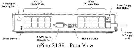
ePipe is equipped with a Kensington Security Slot for physical security The slot is located at the rear of the ePipe indicated by the Kensington Security symbol (see below). Further information and ordering of Kensington Slot Security accessories is available from the Kensington web site.


![]()
about ePipe | products | solutions | support | information center | contact us
Copyright © 2002 ePipe Pty. Ltd. All rights reserved.